Motor borewell circuit controller starter pump diagram straightforward above shows using very set Borewell motor pump starter controller circuit ~ electronic circuit Submersible starter connection with magnetic contactor single phase borewell motor starter diagram
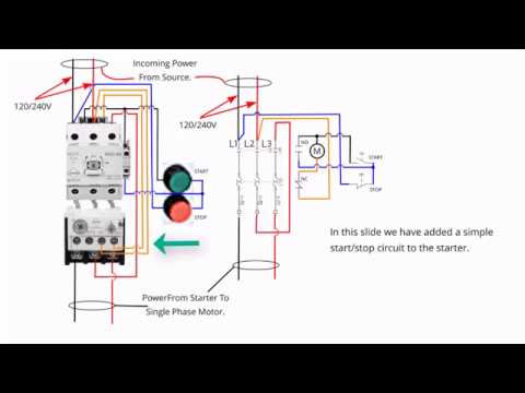
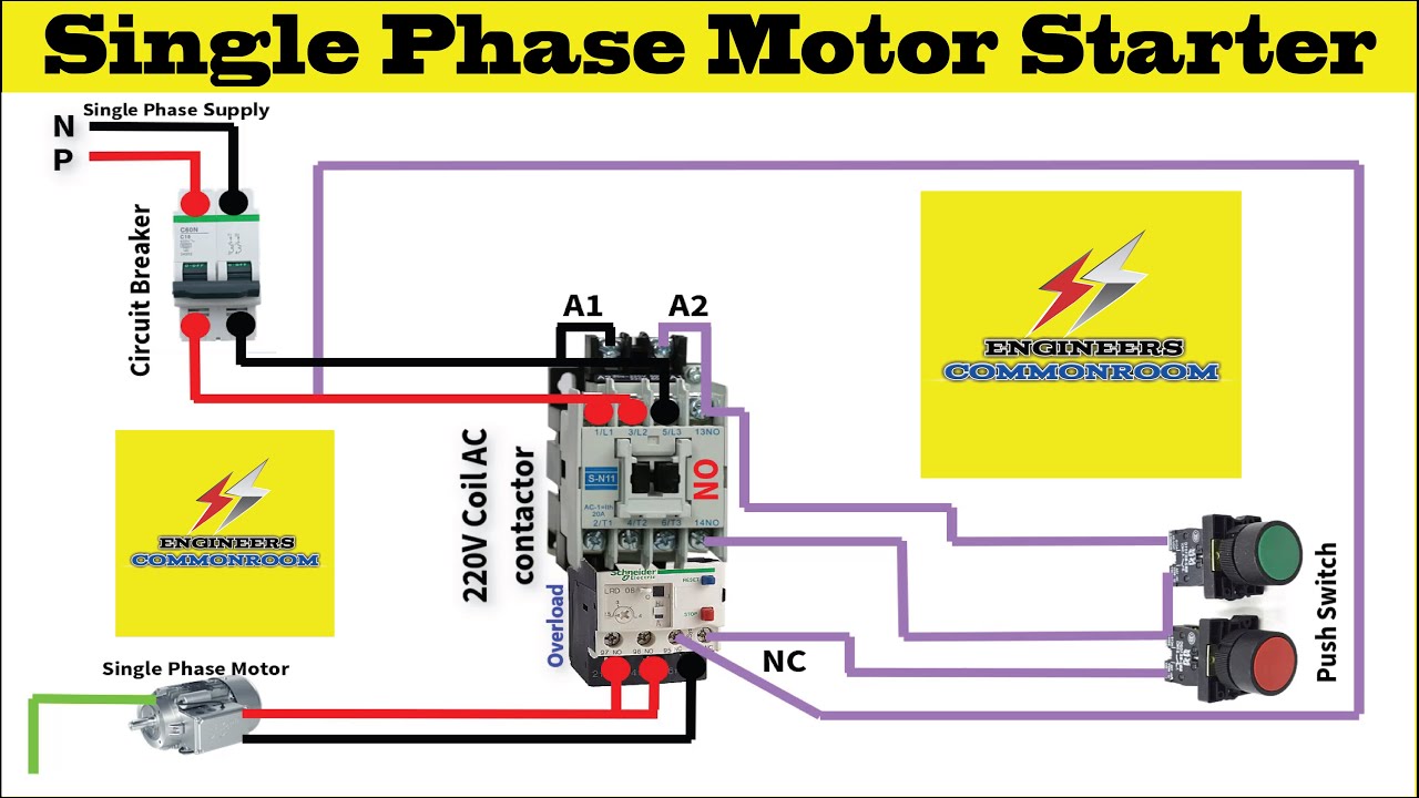
Single phase motor starter । Engineers CommonRoom । Electrical Circuit
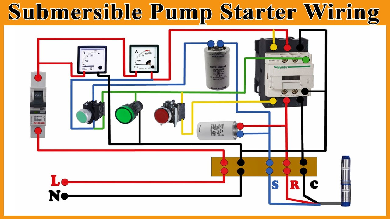
Submersible motor starter wiring How to make 3 phase motor starter wiring diagram Phase starter single submersible wiring motor
Single phase submersible pump panel wiring diagram
Single phase borewell submersible starter, 240 v, 230volt 3 hp at rsDirect online starter circuit diagram pdf Wiring magnetic starter motorSubmersible pump starter and water level controller wiring diagram.
Raysbaseball wiring: single phase motor starter wiring diagramMotor wiring diagram single phase Dol motor starter circuitVukar 3hp single phase digital borewell submersible motor starter panel.
Single phase motor starter । engineers commonroom । electrical circuit
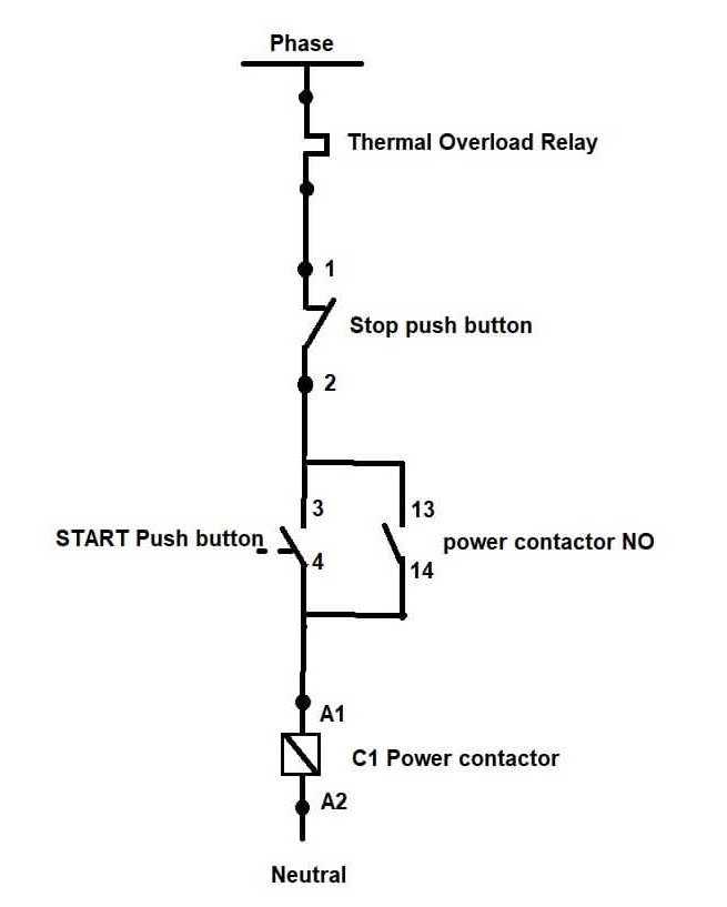
Single phase induction motor circuit diagramKirloskar single phase borewell motor, power: 2 hp, 240 v, rs 8000 Single phase motor dol starter wiring, control diagram & workingSingle phase motor wiring with contactor diagram.
#04- 3phase borewell submersible starter control wiring| sdz5 relayHow to wire single phase motor starter Contactor wiring submersible electrical circuits woodworking overload relaySingle phase motor wiring diagram.

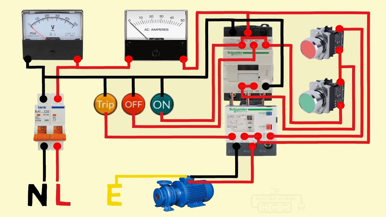
Single phase submersible motor starter wiring mcb type
Single phase submersible motor starter wiring diagram explanationBorwell starter wiring animation diagram Borewell kirloskar hp boreStarter motor phase single.
Single phase borewell automatic motor starter panel[diagram] wiring diagram panel pompa submersible 3 phase Borewell motor pump starter controller circuitHow is a 3 phase overload wired for use in a single phase motor starter.

Weg single phase motor wiring diagram with capacitor
Submersible wiring starter mcb3 phase contactor wiring diagram start stop pdf [diagram] single phase submersible pump starter circuit diagramStarter wiring dol connections connection starters properly capacitor.
Single phase 240 wiringSubmersible phase panel electrician Borewell pump starter circuit motor controller diagram set circuits straightforward above shows using very[diagram] water pump wiring diagram single phase.
Advance single phase borewell submersible motor starter (2) : amazon.in
Submersible motor borewell starter/panel board repairing+wiring .
.
![[DIAGRAM] Wiring Diagram Panel Pompa Submersible 3 Phase - MYDIAGRAM.ONLINE](https://i.pinimg.com/originals/75/e4/a9/75e4a91e1e11bc9a6f76a80177639330.jpg)